Technology
Igniton (eNPQ quasi-particle) technology was originally developed in the 1990’s, and in 1995 the lab was established at CERN facility (Switzerland) with much of the hardware to verify and measure the eNPQ quasi-particle named “ignitons” rented from CERN. The current operation is in Colorado.
The component stages of the eNQP (Ignitons) characterization system are from the Swiss laboratories, that were used until two years ago, when the necessary data on the nature of the quasi-particles and their industrial application had been collected, and the current equipment was designed, constructed and established in Colorado.
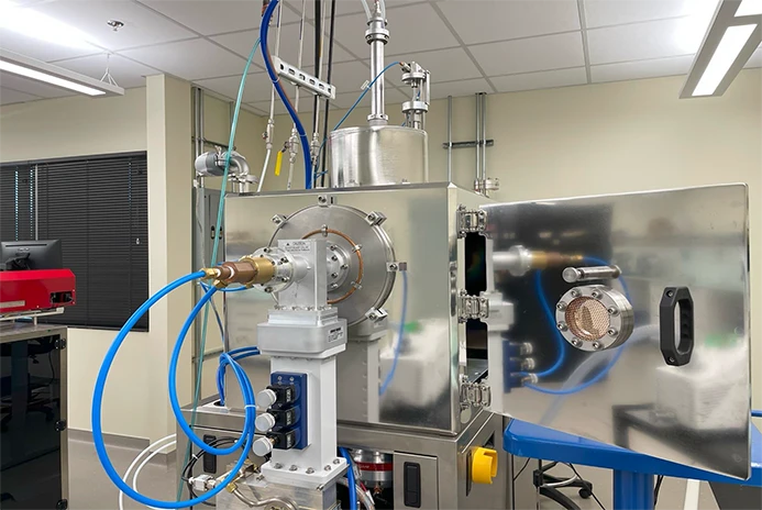
Current ignitons concentration and stabilization equipment
Hot plasma was replaced by cold plasma which allowed designing of much more energy efficient and smaller equipment
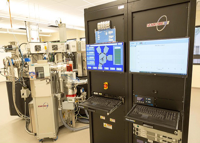
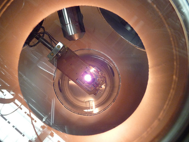
High vacuum cold plasma with coherent photonic stream complex using Si-wafers with quantum well nano-layers
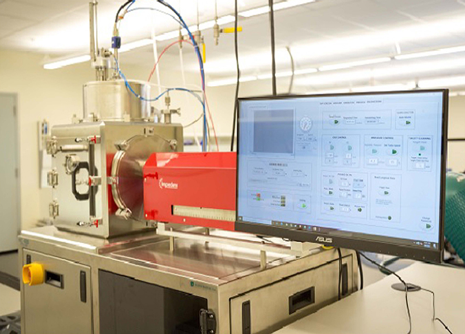
Direct igniton deposition equipment focusing on protons’ gray peripheral region
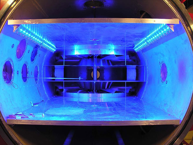
Computer control unit and vacuum plasma chambers
Direct igniton deposition into protons in the molecule mix
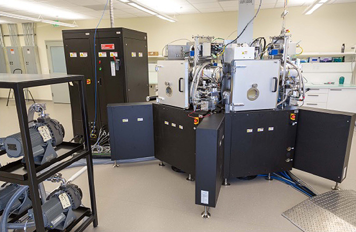
Igniton Embedding Unit
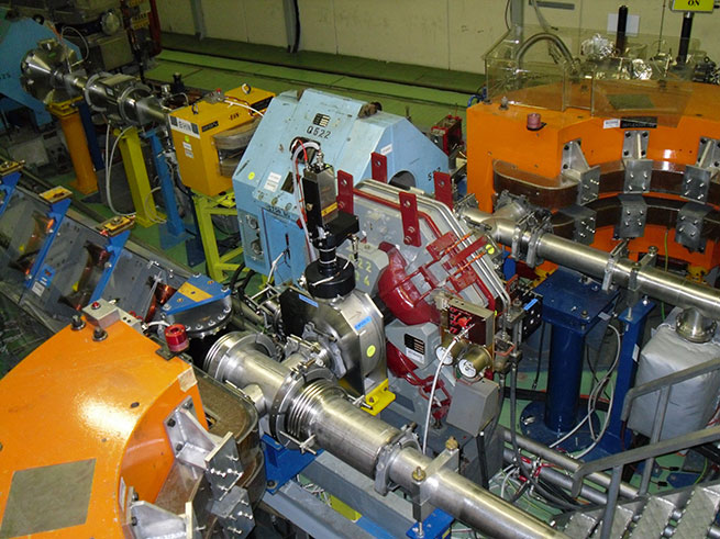
Original ignitons (eNQP) characterization systems
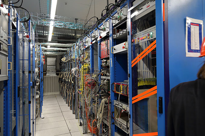
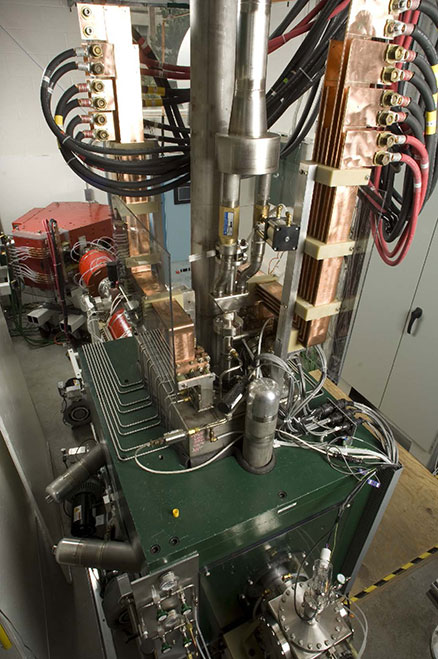
Electronic Control and Counting Systems – Data I/O systems, cascade particle counters, signal amplification systems, radio frequency generator drivers, network systems, sensor and process control
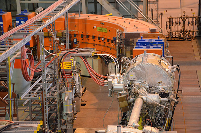
eNQP acceleration stage – Sequential deflectors, and final target
Detection (Stage 1) – Frequency discriminator, tuner and pre-modulation
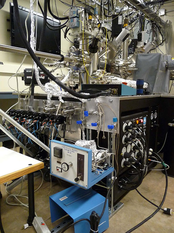
Light-matter interaction – Laser sample disintegration. The sample is disintegrated with laser power the particle packets (including eNQP), isolated and conveyed into the circuit
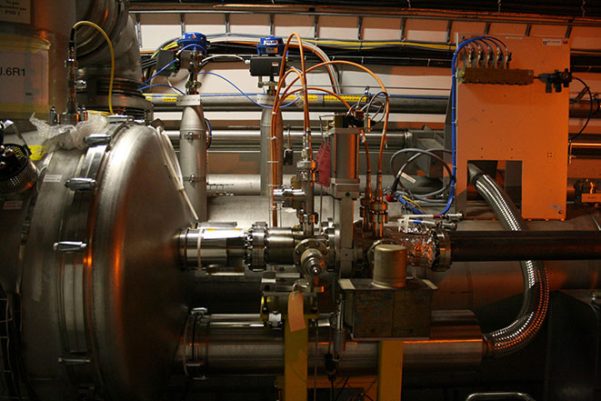
Hot plasma resonance chamber – Sample post volatilisation section. The tritiated gases are injected into this chamber and ionised. As the particle packets obtained from the volatilisation of the matter to be characterised pass through, the eNQPs are highlighted by resonance and labelled for subsequent acceleration.
Vertical magneto-static/RF deflector – Particle packets are deflected towards the separator to split the eNQPs from the transport particles
Splitter – Separation system between transport particles and eNQP. Pre-acceleration stage.
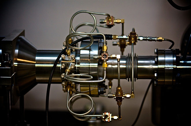
Mixer – eNQP acceleration stage. eNQP mixing with transport waves. Radio frequency stage
Tritium Line – Detail of one of the injectors
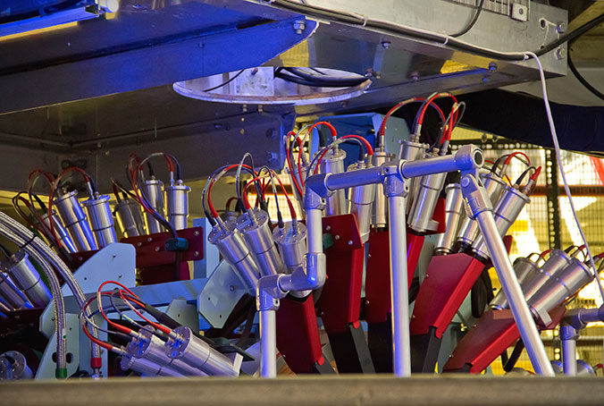
eNQP detectors array – eNQP detection stage, referred to as ‘Exosphere’. The detectors are geometrically positioned in a spherical array, with electronically controlled variable focus
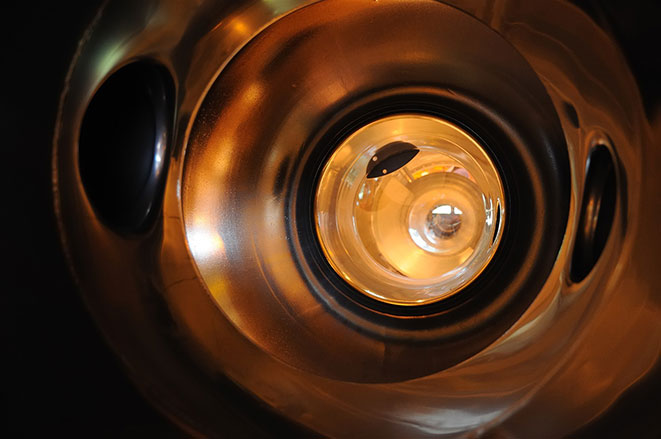
Detectors Stage – Detail of one of the eNQP detectors. GeGaNd-A925T lens window
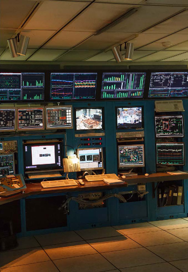
Control Room – Measurement Monitoring Set